 MONKEY BUSINESS IMAGES / MONKEY BUSINESS / THINKSTOCK
Prevent Technique Errors
The use of sound radiographic principles and improved technique will help clinicians produce diagnostically useful images.
Bitewing radiographs are a primary source of adjunctive information in the detection and diagnosis of dental caries.1 In addition to caries detection, serial bitewings can be compared to identify crestal bone changes, as well as horizontal and vertical bone loss to aid in the diagnosis of periodontitis.1 Unlike periapical radiographs, bitewings display the crowns of teeth and crestal bone in both arches. According to the American Dental Association, bitewing radiographs should be used to help detect interproximal caries in the context of patient risk factors, age, and information gleaned from previous radiographs.2
The exposure geometry used with bitewing radiography enhances the ability to identify interproximal caries that are not readily detectable by other means. The diagnostic quality of any X-ray, however, depends on the quality of the radiographic technique. Research has shown that the majority of retakes are due to poor image quality.3 Errors in density and contrast can limit a practitioner’s ability to capture the maximum amount of information that may be available.1 Inappropriate exposure parameters can easily be corrected by displaying a wall-mounted technique chart that includes information regarding appropriate exposure settings.
Digital-based systems typically include software that enhances the image quality of problematic exposures, thus avoiding the need to re-expose the patient to ionizing radiation. The choice of digital detector, or receptor and geometrical alignment device can also introduce errors. This article will discuss the characteristics of an error-free image and how to determine the cause of common technique errors, as well as solutions to fix these errors.
PERFORMANCE CRITERIA
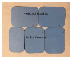
A bitewing survey is typically composed of four horizontal projections, two on each side of the mouth (premolar and molar).1 One exception is when vertical bitewings are indicated (or when larger detectors are used). Vertical bitewings are often indicated in patients where current or past periodontitis is suspected so as to better reveal the relationships of the teeth to interproximal crestal bone levels. Furthermore, a bitewing survey using vertical bitewings may require three bitewings per side to encompass the entire areas of interest (Figure 1). Another exception is when a single size 3 detector is used on each side of the mouth. While this technique reduces radiation exposure, it may not depict the interproximal areas of all teeth without image overlap.
Regardless of the devices or receptors used, it is important to focus on key performance criteria when exposing bitewing radiographs, such as:
- The maxillary and mandibular arches should be equally imaged.
- The premolar image should display the distal surfaces of the maxillary and mandibular canines.
- The molar image should show the distal of the second premolar and completely include the terminal molars on each side of the patient’s mouth.
- In the premolar image, there should be no overlap of the distal surface of the first premolars with the mesial surfaces of the second premolars.
- In the molar exposure, there should be no overlap of the distal surface of the maxillary first molars and the mesial surfaces of the second molars (Figure 2).
![Radiographic Technique]()
FIGURE 2. These horizontal bitewings provide open interproximal views of adjacent teeth (no overlapping) appropriate for each image.
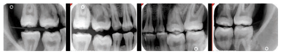
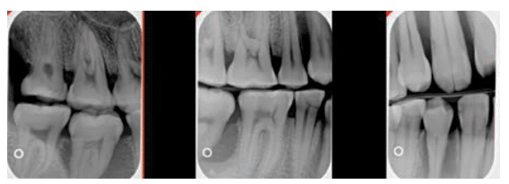
Figure 3 displays a half-mouth example of vertical bitewings. The number of vertical bitewings may range from two to three per side, depending on how many teeth are present. Here, a size 1 detector was used to display the interproximal area between the canines and first premolars. The middle image should depict the interproximal spaces between the first and second premolars, as well as between the second premolars and the first molars. The molar image displays the interproximal spaces between the first, second, and third molars.
PROJECTION GEOMETRY
One of the most common errors when exposing bitewing images is failing to prevent horizontal overlapping. Horizontal overlap is a result of the X-ray beam not passing through the open interproximal area at right angles to a properly positioned detector. Correcting this error on bitewings can usually be achieved by inclining the tubehead in a more mesial or distal direction. The “same lingual opposite buccal” rule can be used to determine which direction the tubehead and/or receptor-holding device should be adjusted. In a normal anatomical relationship, the cusps should appear almost directly on top of one another radiographically. If they don’t, adjust the tubehead in a mesial or distal direction. If the lingual cusp appears mesial to the facial cusp, the tubehead was angled too far in the mesial direction in relation to the interproximal contact. To correct this horizontal overlap, the tubehead needs to be shifted horizontally in a distal direction. If the lingual cusp was distal to the facial cusp, then shift the tubehead horizontally in the mesial direction to open the interproximal area of interest (Figure 4).
Vertical angulation errors may also produce a diagnostically unacceptable bitewing. The “buccal object” rule may be used to help correct the angulation. This rule states that a buccal object will appear in the same direction that the beam is overly angulated. Thus, in the bitewing projection, the images of the arches may be shifted up or down depending on vertical angulation. This problem can be eliminated if the vertical angle of the tubehead is positioned in a +10° angulation (ie, the tubehead beam is angled slightly downward when the patient’s occlusal plane is parallel to the floor). If a beam alignment device is used, then the operator positions the device in the mouth so that the beam is pointing slightly down (Figure 5).
If the beam is pointing up (Figure 6), the holder isn’t positioned correctly. The operator should determine why this is happening and reposition the biteblock in the mouth to achieve an appropriate vertical angle.
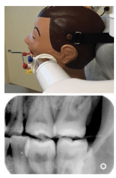 FIGURE 4. This X-ray beam was angled too much to the distal.
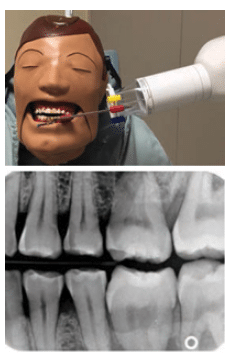 FIGURE 5. Correct vertical alignment for the tubehead.
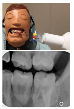 FIGURE 6. Incorrect vertical alignment for tubehead arch.
RECEPTOR PLACEMENT
Detector placement errors often occur because the receptor is uncomfortable. To improve comfort, the receptor can be repositioned more toward the midline of the palate or tongue to avoid placement too close to the alveolar ridges. Another receptor placement error is not positioning the detector to image the distal of the canine (Figure 7). This is a common problem in small mouths. If the detector cannot be positioned more mesially, attempt to position the entire detector more toward the center of the mouth by displacing the tongue to the contralateral side. This provides more anterior space for the mesial margin of the detector and can induce gagging. Asking patients to hold their breath or concentrate on breathing through their noses can ease the gagging reflex.
CONE CUTS AND COLLIMATOR CENTERING
Collimator cuts (also known as cone cuts) result from incorrect centering of the collimator over the receptor and its holder apparatus, if the latter is in use. Cone cuts are fairly common when tightly confined X-ray beams characterized by rectangular collimation are used (Figure 8). Regardless of whether a beam alignment device is implemented, collimator cuts will occur if the beam cross-section fails to expose the entire receptor. To decrease the likelihood of cone cuts, the radiographer must carefully align properly positioned detectors and holders to assure that the X-ray beam’s cross-section includes the entire receptor.
SOLUTIONS TO COMMON ERRORS
Technique errors most commonly occur due to incorrect placement of the detector, wrong vertical or horizontal alignment of the X-ray beam, or collimator centering. Clinicians should be able to determine the causes of error so they can be corrected.
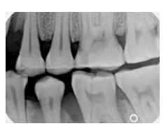 FIGURE 7. Incorrect detector placement with receptor positioned too far to the distal.
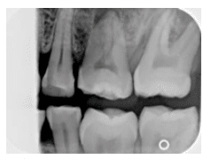 FIGURE 8. An incorrect orientation of a rectangular collimator results in a cone cut. An incorrectly positioned round beam would display a semicircular cone cut.
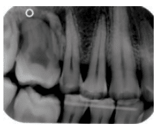 FIGURE 9. This X-ray displays more of the maxillary arch than the mandibular arch.
In Figure 9, the image displays more of the maxillary arch than the mandibular arch. A good diagnostic image would display equal amounts of the maxillary and mandibular arches. Additionally, the mandibular crestal bone was not imaged. The error seen in Figure 9 is mostly likely due to the vertical angulation being positioned too steeply (ie, collimator aimed too far downward). To correct this error, the vertical alignment of the collimator should be repositioned at +10° figured from an occlusal plane that is parallel with the floor.
Figure 10 displays a premolar bitewing image. The projection is missing the distal of the maxillary canine and mesial of the maxillary first premolar. There is slight horizontal overlap between the maxillary premolars. Is this a detector placement error or horizontal angulation error? This error may have occurred because of incorrect detector placement and/or incorrect horizontal angulation. The detector may not be placed sufficiently mesial and/or the tubehead may be aimed too mesially, thus projecting the mesial of the premolar off the receptor and causing horizontal overlap.
Figure 11 displays a bitewing image that has a clear diagonal area in the right corner, thus preventing the display of diagnostic information from the maxillary second molar. This error occurs due to the rectangular collimator being seated improperly in the indentations of the aiming ring. It can be prevented by checking both sides of the aiming ring for complete placement of the collimator into the ring indentations. To correct, the edges of the rectangular collimator should be rotated to fit into the alignment ring notches.
Figure 12 displays a premolar bitewing in which the distal of the canine and first premolars are not imaged in the projection. This error is due to improper detector placement, with the receptor positioned too far to the distal. This is a common problem in small mouths. To correct this error, first try to place the detector more mesially. If impossible, attempt to position the detector more toward the center of the mouth by displacing the tongue to the contralateral side, thereby providing more anterior space for the mesial margin of the detector.
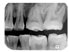 FIGURE 10. A premolar bitewing image that is missing the distal of the maxillary canine and mesial of the maxillary first premolar.
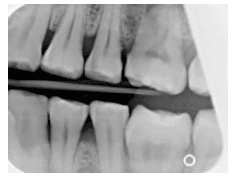 FIGURE 11. This bitewing image has a clear diagonal area in the right corner, thus preventing the display of diagnostic information from the maxillary second molar.
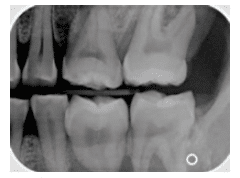 FIGURE 12. A premolar bitewing in which the distal of the canine and first premolars are not imaged in the projection.
FUTURE TECHNOLOGY
For many decades, bitewing radiographs have been highly useful in caries diagnosis, especially for detecting interproximal caries. In recent years, however, panoramic radiographic technology has improved and now produces images comparable to traditional bitewings. An in vitro study conducted by Abu El-Ela et al4 compared digital images for the detection of interproximal caries using photostimulable receptors, complementary metal oxide semiconductor receptors, and a panoramic X-ray unit. Their findings indicated there was no significant difference between the three radiographic bitewing techniques for the detection of enamel caries. A similar study was conducted by Abdinian et al5 that compared a variety of panoramic radiographs with intraoral bitewing images for the detection of interproximal caries. They found that the improved panoramic and extraoral bitewing radiographic images were better than conventional panoramic images. In contrast, Kamburoglu et al6 reported in 2012 that intraoral bitewing images were better for diagnosing interproximal caries compared with the extraoral bitewing and panoramic images. The difference in results may be due to improvements in imaging technology since 2012. Thus, continued research should be conducted to assess new technology as it is introduced.
CONCLUSION
Contemporary dental radiography continues to incorporate new techniques and technology for the detection of anatomical changes suggestive of disease or healing.7 Regardless of technology, clinicians must use sound radiographic principles and strive to improve their skills in order to consistently produce diagnostically useful images while minimizing patient
exposure to ionizing radiation.
References
- White SC, Pharoah MJ. Intraoral projections. In: Oral Radiology: Principles and Interpretation. Philadelphia: Elsevier Mosby; 2014:91–130.
- American Dental Association Council on Scientific Affairs: Dental Radiographic Examinations: Recommendations for Patient Selection and Limiting Radiation Exposure. Available at:?ada.org/sections/professionResources/ pdfs/Detnal_Radiographic_Examinations_2-12.pdf. Accessed May 19, 2016.
- Platin E, Janhom A, Tyndall D. A quantitative analysis of dental radiography quality assurance practices among North Carolina dentists. Oral Surg Oral Med Oral Pathol Oral Radiol Endod. 1998;86:115–120.
- Abu El-Ela WH, Farid MM, Mostafa MS. Intraoral versus extraoral bitewing radiography in detection of enamel proximal caries: an ex vivo study. Dentomaxillofac Radiol. 2016;45:20150326.
- Abdinian M, Razavi SM, Faghihian R, Samety AA, Faghihian E. Accuracy of digital bitewing radiography vs different views of digital panoramic radiography for detection of proximal caries. J Dent (Tehran). 2015; 12:290–297.
- Kamburoglu K, Kolsuz E, Murat S, Yüksel S, Ozen T. Proximal caries detection accuracy using intraoral bitewing radiography, extraoral bitewing radiography and panoramic radiography. Dentomaxillofac Radiol. 2012;41:450–459.
- Fuhrmann AW. Current practice in conventional and digital intraoral radiography: problems and solutions. Int J Comput Dent. 2006;9:61–68.
From Dimensions of Dental Hygiene. June 2016;14(06):24–28.
