Cone-Beam Computed Tomography
An important tool in radiographic imaging during orthodontic treatment, dental professionals need to understand its inherent benefits, while also considering the risks of increased radiation exposure.
This course was published in the April 2014 issue and expires April 30, 2017. The authors have no commercial conflicts of interest to disclose. This 2 credit hour self-study activity is electronically mediated.
EDUCATIONAL OBJECTIVES
After reading this course, the participant should be able to:
- Discuss how cone-beam computed tomography (CBCT) acquires images.
- Identify the different ways CBCT can be configured.
- Explain CBCT radiography technique.
- List the precautions and risks involved with CBCT use.
Radiographic imaging is an integral component of patient assessment. In orthodontics, its purpose is to provide additional information to support the clinical diagnosis of skeletal and dental conditions, soft tissues, and their inter-relationships. Orthodontic diagnosis and treatment plans, evaluation of growth and development, and assessment of treatment progress have traditionally been achieved from the integration of clinical data with observations obtained from two-dimensional (2D) extraoral radiography—such as panoramic, lateral cephalometric, and hand-wrist images. In addition to these static records, three-dimensional (3D) information and plaster study models of the maxillary and mandibular dental arches have remained the preferred method of documentation. Numerous digital reflective light-based technologies have emerged for recording and storing virtual 3D models of the dentition. These technologies can create various orthodontic appliances that will move teeth and assist with 3D facial surface capture.
The inherent limitations of 2D extraoral radiography for maxillofacial assessment in orthodontics are well known.1–3 These include magnification, disproportional distortion, projective superimposition of anatomical details, error and artifacts due to X-ray projection and patient positioning, and cephalometric measurement error due to inherent difficulties in landmark identification. Understanding the complex anatomic relationships and surrounding structures of the maxillofacial skeleton is necessary during orthodontic treatment planning and management in order to provide the most appropriate therapy from the wide array of treatment options.
Computed tomography (CT) has been available since the late 1970s. Its clinical application in dentistry, however, was limited because of equipment cost, access, and radiation dose considerations. The introduction of cone-beam computed tomography (CBCT) to dentistry in the United States at the turn of the 21st century has provided dental practitioners with low-cost, in-office diagnostic imaging technology capable of demonstrating 3D dental and skeletal relationships. The dramatic increase in the use of maxillofacial CBCT imaging in dentistry over the past 10 years has been accompanied by a shift from a 2D to a 3D approach.
IMAGING ACQUISITION
CBCT imaging comprises two phases—data acquisition and data reconstruction. The first phase involves an X-ray unit connected to an X-ray detector that circles the head of a patient producing 2D radiographic images. The second phase involves reconstructing this series of images into 3D information.4–7
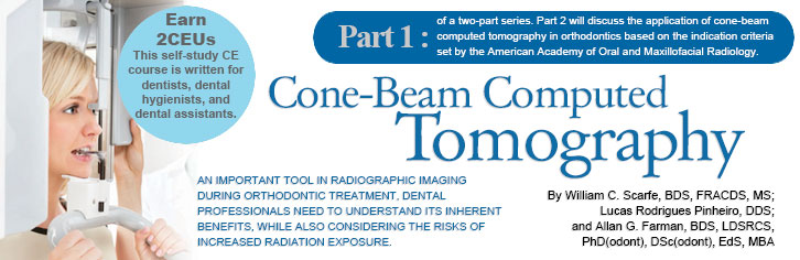
A pyramidal- or cone-shaped X-ray beam is directed toward an area X-ray detector on the opposite side of a patient’s head. The two components are attached by an arm, or gantry. The gantry moves around a fixed, imaginary fulcrum located in the middle of the area to be imaged. As it rotates, the X-ray tube makes multiple exposures during a single synchronous partial or full rotation. This varies from a traditional multi-detector CT, which uses a continuously rotating fan-shaped X-ray beam as the patient moves through the region of the exposure. From this motion, individual image sections or slices of the patient are produced and then stacked to obtain a 3D representation.
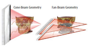
For CT, each slice requires a separate scan and separate 2D reconstruction. In CBCT, multiple 2D projection images are acquired (Figure 1). The X-ray beam projects onto an area of the face—also known as field of view (FOV)—that is often confined to a specific region of interest (ROI) by collimation. One scan can result in anywhere from 150 to more than 1,000 individual 2D basis images. These images are referred to as the projection data (Figure 2).
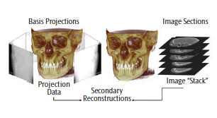
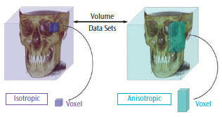
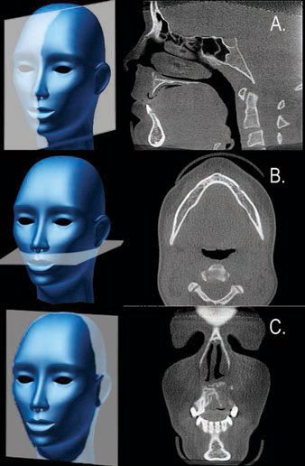
Sophisticated software programs process the projection data to map the amount of radiation absorbed at a specific location in the patient’s head, which generates a 3D volumetric data set composed of cuboidal volume elements (voxels). Voxel dimensions are dependent on the pixel size of the area detector vs the multi-detector CT, which is dependent on slice thickness. As the resolution of the area detector is submillimeter, CBCT units provide voxel resolutions that are isotropic—or equal in three orthogonal dimensions (Figure 3). The default presentation of the dataset is a series of contiguous thin images in three orthogonal planes, including sagittal, axial, and coronal (Figure 4).
EQUIPMENT CONFIGURATIONS
Many manufacturers offer CBCT imaging devices with several unit configurations.8,9 From the clinical viewpoint, units are differentiated according to the orientation of the patient during image acquisition. The functional perspective assesses whether the unit is a panoramic platform offering additional small to medium FOV CBCT imaging “hybrid” functionality, or a dedicated system with an FOV that can partially cover the maxillofacial region, the whole maxillofacial region, or even the whole head.
The majority of CBCT units scan patients in a standing and/or sitting position. Few can scan patients who are in a supine position. Supine units occupy a larger surface area and may not be accessible for patients with physical disabilities. Standing units may not be adjustable to accommodate patients in wheelchairs. Seated units are the most comfortable; however, fixed seats may not allow scanning of patients with physical disabilities or those in wheelchairs. Perhaps more important than patient orientation is the head restraint mechanism, which is necessary to restrict patient movement during the scan and can minimize the attained spatial resolution.10
CBCT systems are categorized into standalone or hybrid multimodal systems. Multimodal units combine digital panoramic and/or cephalometric radiography with a small to medium FOV CBCT system. By combining functions, these units reduce the overall office footprint for imaging equipment and are less expensive than standalone units, as existing robotic panoramic platforms can be re-engineered using small, cost-effective detectors.
TECHNIQUE
CBCT radiography shares a number of procedural and operational similarities with panoramic radiography. There are two important differences between the imaging techniques. First, CBCT imaging may require more adjustment of exposure settings during use. Second, CBCT exposes patients to the highest radiation dose compared to current dental imaging procedures. Oral health professionals have an ethical responsibility to become familiar with the technical and operational aspects of CBCT, as well as to understand the scientific validity and health risks of its applications.
The operation of CBCT equipment is similar to panoramic radiography. In panoramic radiography, kilovoltage (kV) is often adjusted for an individual patient depending on age, state of edentulism, and size. However, most CBCT units provide numerous choices in available exposure settings. Appropriate selection of these parameters is necessary to optimize image quality and minimize radiation exposure. Clinicians using CBCT must have a thorough understanding of the following operational settings and their effects on image quality and radiation safety.11
- Exposure: CBCT units are manufactured with fixed exposure settings or they allow manual adjustment of peak kilovoltage (kVp) and/or milliamperage (mA). Operators of CBCT units with adjustable exposure settings should realize that these parameters directly impact both image quality and patient radiation dose. Careful selection is required to fulfill the as low as reasonably achievable (ALARA) or as low as practical (ALAP) principles.12,13 Adjustment should be based on the size of the patient and comply with the manufacturer’s recommendations. While mA may be increased to compensate for an increase in patient size, the patient-effective dose increases proportionately almost in a 1:1 ratio. Adjustment of kVp has an even greater effect on dose than does mA, with a reduction of approximately 20% decreasing radiation dose by nearly 40% if all parameters remain the same.14
- Time: The total number of basis images comprising the volumetric dataset for a single scan of a specific CBCT unit may be fixed or variable, depending on the unit. A greater number of basis images provides more information to reconstruct the image and generally produces images with better contrast, decreased graininess or noise, a “smoother” look, and potentially less metallic artifacts. Clinicians need to remember that the longer the scan, the greater the radiation exposure, and the more time needed for primary reconstruction.15
- Resolution: There are two types of image resolution—spatial resolution and contrast resolution. The former refers to the ability of the CBCT unit to show fine details, such as demonstrating the periodontal ligament space or a narrow root canal. Many CBCT devices allow choice of this setting. All devices produce images with submillimeter nominal voxel resolution. As a rule of thumb, tasks requiring high spatial resolution in orthodontics (eg, determining if an unerupted tooth is ankylosed or if a tooth root surface has external resorption) should be performed at a voxel resolution of 0.2 mm or finer. Depending on the unit, the choice of lower resolution may result in a reduced patient radiation dose.16Contrast resolution is the ability to discriminate between different types of tissues with minor differences in X-ray absorption and display them as differences in gray levels. While most CBCT units are capable of capturing 12-bit to 16-bit gray-scale images, numerous factors limit the contrast resolution of CBCT. These include noise, the resolving ability of the area detector, the display characteristics of the monitor, and inherent discriminatory limitations of the human visual system.
- Rotation angle: Also known as trajectory arc, this is the angular rotation of the gantry—with the X-ray tube on one end and the detector on the other. The CBCT system should employ a 360° rotation, ensuring ample data for the software algorithm to reconstruct the dataset. Some units have a variable rotation arc, while others have a fixed but limited rotation angle. Data obtained with limited rotation angle CBCT units must be extrapolated to provide a full volumetric dataset. The images produced by this method may have greater noise and suffer from additional artifacts.
- FOV: This refers to the volume of tissue in the patient’s head that is irradiated during exposure. Few CBCT units with a fixed FOV are still produced. The view should be adjusted to cover only the ROI. As a trend for the same CBCT unit, the larger the FOV, the greater the radiation dose to the patient. However, comparable FOV units on different CBCT units produce a range of radiation exposures to the patient.
LIMITATIONS AND PRECAUTIONS
While the dental applications of CBCT imaging have expanded tremendously, the technology has limitations related to the CB projection geometry, relatively low exposure settings, and limited detector sensitivity and contrast resolution. CBCT images have inherent “noise” that reduces image clarity, and are also unable to record soft tissue. Image quality is also affected by image artifacts, such as streaking, shading, rings, and distortion. Streaking and shading artifacts—due to high areas of attenuation (such as metallic restorations) and inherent spatial resolution—may limit adequate visualization of structures in the dento-alveolar region.
CBCT imaging uses ionizing radiation, a known carcinogen. The general public’s awareness of the increased radiation dose and risks associated with CBCT, particularly in orthodontics, was catapulted with the publication of a front page article in the New York Times in 2010.17 Recent scientific reports have increased professional concerns over the potential association between radiation exposure and cancer. These reports have also raised questions about using ionizing radiation for diagnostic dental imaging.18–20 While these results are controversial,21,22 the use of any radiographic technique demands patient exposure be justified clinically and that principles and procedures are implemented to minimize patient radiation exposure while optimizing maximal diagnostic benefit.23
RADIATION RISK
Effective dose, reported in Sieverts (Sv), is used to calculate whole-body dose and provides a measure of relative risk from exposure to ionizing radiation. Effective dose is calculated by measuring absorbed dose in specific sites within tissue and organs, multiplying these doses by a factor representing that tissue’s relative susceptibility of radiation, and then adding the numbers.24 Tissues found in the head and neck region—most important, the salivary glands, lymphatic nodes, muscle, and oral mucosa—have recently been included in this calculation.25 While effective dose is the currently accepted index of radiation dose risk, there is disagreement about whether this is a valid measurement because it is based on an arbitrary consensus of relative tissue sensitivity. Furthermore, it does not consider patient susceptibility variations, such as sex and age.
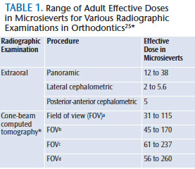
The actual risk for low-dose radiographic procedures, such as maxillofacial radiography, is difficult to assess and is based on conservative assumptions. Although radiation may cause cancer at high doses, there are no data to establish unequivocally the occurrence of cancer following exposure to low doses—below 0.1 Sv (100,000 ?Sv). In the realm of dental diagnostic radiology (10 ?Sv to 300 ?Sv), including CBCT (Table 1),25 it is generally accepted that any increase in dose, no matter how small, results in an incremental increase in risk.26 Therefore, there is no safe limit for radiation exposure in orthodontic diagnostic imaging. Every exposure cumulatively increases the risk of cancer.
The risk associated with various dental radiographic procedures, specifically CBCT imaging, has been compared to the radiation dose imparted by a “baseline” imaging modality or to US average background equivalent radiation time. Unfortunately, the base unit of comparison for these determinations is variable and not absolute. This means, depending on the panoramic image dose used for the comparison (eg, equipment manufacturer and model, film vs digital acquisition), the risk for CBCT can be reported either conservatively or liberally. Recently, radiation risk for medical imaging examinations is being reported as relative to a range of exposures below the value, at which one in 1,000 individuals will develop cancer.26 This is referred to as relative radiation level27 and provides a way to compare the relative risk between different imaging examinations. The additional advantage of this classification is that it provides a method to compare risk of procedures—especially in children, for whom radiation exposure poses a far greater risk than adults.
CHILDREN AT GREATEST RISK
In the case of orthodontics, which involves imaging young patients, exposure to ionizing radiation from CBCT imaging is of particular concern for five reasons:
- Almost all CBCT units impart higher doses than the range reported from digital panoramic, lateral cephalometric, or four-image bitewing intraoral radiography.28,29
- Young patients are more radiosensitive than adults.30
- Young patients have a longer expected lifetime for the effects of radiation exposure to present as cancer.
- Organ doses, particularly the salivary glands, and effective doses for children with CBCT are approximately 30% higher than for adolescents with the same exposure.31
- Use of equipment and exposure settings designed for adult use can result in excessive radiation exposure for a smaller patient.
Because of these considerations, children may be two times to 10 times more sensitive to radiation carcinogenesis than adults.32,33 This translates to a three times to five times higher mortality risk for children than for adults with the same exposure.24,30
SUMMARY
Maxillofacial CBCT imaging provides accurate, submillimeter resolution images of diagnostic quality, enabling 3D visualization of the complex osseous structures of the maxillofacial region. While technically easy to perform, operators of CBCT equipment should be aware of the effects that the additional exposure settings have on both image quality and patient radiation dose. CBCT imaging exposures result in higher patient radiation doses than most other imaging procedures in dentistry. In addition, because CBCT imaging in orthodontics involves mostly young patients, oral health professionals must be mindful that children are more sensitive to radiation exposure than adults.
ACKNOWLEDGMENTS
Some of this information was provided with permission from the American College of Radiology (ACR) and taken from the ACR Appropriateness Criteria®. The ACR is not responsible for any deviations from the original ACR Appropriateness Criteria content. The authors wish to acknowledge the contributions made by the members of an expert panel convened by the American Academy of Oral and Maxillofacial Radiology to provide clinical recommendations regarding the use of CBCT in orthodontics.
REFERENCES
- Baumrind S, Miller D, Molthen R. The reliability of head film measurements. 3. Tracing superimposition. Am J Orthod. 1976;70:617–644.
- Moyers RE, Bookstein FL. The inappropriateness of conventional cephalometrics. Am J Orthod. 1979;75:599–617.
- Johnston LE. A few comments on an elegant answer in search of useful questions. Seminars in Orthodontics. 2011;17(1):13–14.
- Scarfe WC, Farman AG. Cone-beam computed-tomography: a paradigm shift for clinical dentistry. Australasian Dental Practice. 2007:102–110.
- Scarfe WC, Farman AG. What is cone-beam CT and how does it work? Dent Clin North Am. 2008;52:707–730.
- Scarfe WC, Farman AG. Cone-beam computed tomography: visualization, interpretation and utilization. In: White SC, Pharoah MJ, eds.: Oral Radiology Principles & Interpretation. 6th ed. St Louis: Elsevier. 2008;225–243.
- Angelopoulos C, Scarfe WC, Farman AG. A comparison of maxillofacial CBCT and medical CT. Atlas Oral Maxillofac Surg Clin North Am. 2012;20:1–17.
- Nemtoi A, Czink C, Haba D, Gahleitner A. Cone beam CT: a current overview of devices. Dentomaxillofac Radiol. 2013;42:20120443.
- Scarfe WC, Li Z, Aboelmaaty W, Scott SA, Farman AG. Maxillofacial cone beam computed tomography: essence, elements and steps to interpretation. Aust Dent J. 2012;57(Suppl 1):46–60.
- Bontempi M, Bettuzzi M, Casali F, Pasini A, Rossi A, Ariu M. Relevance of head motion in dental cone-beam CT scanner images depending on patient positioning. International Journal of Computer Assisted Radiology and Surgery. 2008;3(3-4):249–255.
- Carter L, Farman AG, Geist J, et al. American Academy of Oral and Maxillofacial Radiology executive opinion statement on performing and interpreting diagnostic cone beam computed tomography. Oral Surg Oral Med Oral Pathol Oral Radiol Endod. 2008;106:561–562.
- National Council on Radiation Protection & Measurements. NCRP Report No. 145, Radiation Protection in Dentistry. Available at: ncrponline.org/Publications/Press_Releases/145press.html. Accessed March 18, 2014.
- Gelskey DE, Baker CG. The ALARA concept. Population exposures from x-rays in dentistry—as low as reasonably achievable? J Can Dent Assoc. 1984;50:402–403.
- Palomo JM, Rao PS, Hans MG. Influence of CBCT exposure conditions on radiation dose. Oral Surg Oral Med Oral Pathol Oral Radiol Endod. 2008;105:773–782.
- Roberts JA, Drage NA, Davies J, Thomas DW. Effective dose from cone beam CT examinations in dentistry. Br J Radiol. 2009;82:35–40.
- Qu XM, Li G, Ludlow JB, Zhang ZY, Ma XC. Effective radiation dose of ProMax 3D cone-beam computerized tomography scanner with different dental protocols. Oral Surg Oral Med Oral Pathol Oral Radiol Endod. 2010;110:770–776.
- The New York Times. Radiation worries for children in dentists’ chairs. Available at: nytimes.com/2010/11/23/us/23scan.html?pagewanted=all. Accessed March 18, 2014.
- Hujoel P, Hollender LG. More than 5 full-mouth radiographic series increases intracranial meningioma risk. J Evid Based Dent Pract. 2005;5:162–163.
- Longstreth WT Jr, Phillips LE, Drangsholt M, et al. Dental X-rays and the risk of intracranial meningioma: a population-based case-control study. Cancer. 2004;100:1026–1034.
- Claus EB, Calvocoressi L, Bondy ML, Schildkraut JM, Wiemels JL, Wrensch M. Dental X-rays and risk of meningioma. Cancer. 2012;118:4530–4537.
- White SC, Hildebolt CF, Lurie AG. Dental x-rays and risk of meningioma. Cancer. 2013;119:464.
- Tetradis S, White SC, Service SK. Dental x-rays and risk of meningioma; the jury is still out. J Evid Based Dent Pract. 2012;12:174–177.
- American Dental Association Council on Scientific Affairs. The use of cone-beam tomography in dentistry: an advisory statement from the American Dental Association Council on Scientific Affairs. J Am Dent Assoc. 2012;143:899–902.
- 1990 Recommendations of the International Commission on Radiological Protection. Ann ICRP. 1991;21:1–201.
- American Academy of Oral and Maxillofacial Radiology. Clinical recommendations regarding use of cone beam computed tomography in orthodontics. [corrected]. Position statement by the American Academy of Oral and Maxillofacial Radiology. Oral Surg Oral Med Oral Pathol Oral Radiol. 2013;116:238-57. Erratum in: Oral Surg Oral Med Oral Pathol Oral Radiol. 2013;116:661.
- The 2007 Recommendations of the International Commission on Radiological Protection. Ann ICRP. 2007;37:1–332.
- American College of Radiology. ACR Appropriateness Criteria. Radiation Dose Assessment Introduction. Available at: acr.org/~/media/a27a29133302408bb86888eafd460a1f.pdf. Accessed March 18, 2014.
- Ludlow JB, Ivanovic M. Comparative dosimetry of dental CBCT devices and 64-slice CT for oral and maxillofacial radiology. Oral Surg Oral Med Oral Pathol Oral Radiol Endod. 2008;106:106–114.
- Ludlow JB, Davies-Ludlow LE, White SC. Patient risk related to common dental radiographic examinations: the impact of 2007 International Commission on Radiological Protection recommendations regarding dose calculation. J Am Dent Assoc. 2008;139:1237–1243.
- Committee to Assess Health Risks from Exposure to Low Levels of Ionizing Radiation; Board on Radiation Effects Research; Division on Earth and Life Studies; National Research Council. Health Risks from Exposure to Low Levels of Ionizing Radiation: BEIR VII Phase 2. 424. Washington DC: The National Academies Press; 2006:424.
- Theodorakou C, Walker A, Horner K, et al. Estimation of paediatric organ and effective doses from dental cone beam CT using anthropomorphic phantoms. Br J Radiol. 2012;85:153–160.
- Brenner D, Elliston CD, Hall E, Berdon W. Estimated risks of radiation-induced fatal cancer from pediatric CT. AJR Am J Roentgenol. 2001;176:289–296.
- Smith-Bindman R, Lipson J, Marcus R., et al. Radiation dose associated with common computed tomography examinations and the associated lifetime attributable risk of cancer. Arch Intern Med. 2009;169:2078–2086.
From Dimensions of Dental Hygiene. April 2014;12(4):60–64.
