Decoding Digital X-Rays
Clinicians must remain up to date on their anatomy knowledge and diagnostic skills to effectively interpret radiographs.
The views expressed in this article are those of the authors and do not reflect the official policy of the United States Air Force, the US Department of Defense, or the US Government.
Digital radiography is an integral part of effective diagnosis and treatment of oral diseases. Normal anatomical structures, however, may sometimes mimic pathology on radiographs. Many areas of the oral cavity can suggest that a serious problem exists once radiographed. Oral health professionals need to refresh their anatomy knowledge and diagnostic skills to adeptly evaluate radiographs.
INCISIVE FOSSA
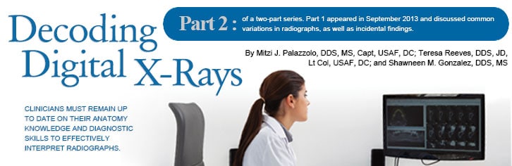
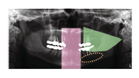
The incisive fossa—an area of thin bone located near the maxillary lateral incisors—is one of the most common anatomical appearances on radiographs that may mimic a disease process. The incisive fossa presents as a decreased radiopacity of bone surrounding the lateral incisor roots. Frequently, the soft tissue of the nose is superimposed over or apical to the apex of the lateral incisor root, making the fossa appear more radiolucent than surrounding bone (Figure 1).1
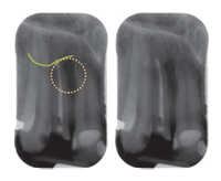
FIGURE 1. These periapicalradiographs show the incisivefossa (circled in yellow) as a diffuse radiolucent area around the root of the right lateral incisor (#7) with the ala (wing) of the nose (green line) superimposed over the apex of the lateral incisor. Note the lamina dura and periodontal ligament space are intact around the entire root, indicating normal anatomy.

FIGURE 2. Anterior periapical radiographs showing a well-localized radiolucent area at the apex of the right lateral incisor (#7). Note that the radiolucent area is continuous with the lamina dura and periodontal ligament space on both images, indicating loss of bone due to tooth origin.
ANTERIOR MANDIBLE
The anterior mandible area is thin facial-lingually and may present radiographically as a diffuse radiolucent area that is more evident on intraoral radiographs (Figure 3A to Figure 3B). Careful evaluation of the lamina dura and periodontal ligament space of the incisor roots will help determine if the anatomy is normal (Figure 4).1

FIGURE 3A. These anterior periapical radiographs show increased radiolucent bone around the roots of the incisors due to thin facial-lingual bone width (circled in yellow).
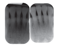
FIGURE 3B. On the left, the anterior periapical area shows intact periodontal ligament space and laminadura. The right radiograph, made with less time to purposely underexpose the area, shows bone evident in the radiolucent area.

FIGURE 4. These periapical radiographs of awell-defined radiolucent area with loss ofthe lamina dura surrounding the right central incisor (#25) indicate bone loss, most likely due to tooth origin
MENTAL FORAMEN
The mental foramen is an opening of the mandibular canal on the facial aspect of the mandible. It appears as a round-to-ovoid, radiolucent entity (Figure 5). In some patients, the mental foramen will be superimposed over the root of the second premolar and may mimic pathosis. Evaluation of the lamina dura and periodontal ligament space is crucial for correct interpretation.1
SALIVARY GLAND
The submandibular salivary gland depression is a normal anatomical landmark where the mandible narrows facial-lingually inferior to the mandibular molars. It accommodates the submandibular salivary gland. Presenting as a well-localized, radiolucent area apical to the mandibular molars and inferior to the lower border of the mandible (Figure 6), this depression does not have a well-defined appearance.1 On a pantomograph, the area may appear more radiolucent due to adjacent radiopaque areas created by the imaging. Superiorly, a diffuse, radiopaque area, which is the ghost image of the opposite ramus, is visible, and in the anterior midline of the pantomograph is the superimposition of the cervical spine (Figure 7). This appearance is within the range of normal.2
AIRWAY

The airway is generally seen on pantomographs that are superimposed over the ramus of the mandible (Figure 8A to Figure 8C). Sometimes, the airway appears radiolucent, causing the angle of the mandible to look “burned out.” This indicates that no information was captured. Burn out should not be confused with pathosis or mandibular fracture. To correct this, another pantomograph should be made using a lower peak kilovoltage (kVp) and milliamperage (mA) setting—purposely underexposing the patient to produce a lighter image (Figure 8B).2 In pantomographic imaging, saturation can caused by overexposure, but is most likely due to a gamma correction setting in the software.
CERVICAL SPINE
Occasionally, the cervical spine is seen on the lateral aspects of the pantomographs, due to technique error. In most cases, the cervical spine is curved, and the anterior arch of the atlas (C1) is superimposed on the condylar neck—giving the impression of an increased radiopacity within the upper aspect of the posterior ramus and neck of the condyle (Figure 9). The best way to avoid this is to ensure proper positioning and use of correct technique. Oral health professionals should ask patients to stand tall and tuck their chins slightly downward. This will help to straighten the cervical spine and prevent the atlas (C1) from superimposing on the ramus.
SETTING ADJUSTMENT
Advanced technology in direct digital pantomographic imaging gives clinicians the opportunity to change settings to match the size and shape of patients’ jaws. For example, when imaging a small/average woman, it may be appropriate to reduce the breadth of the posterior focal trough to a size consistent with most adolescents. The tips discussed previously help to prevent capturing the cervical spine in the image. If appearing in the pantomograph, the cervical spine should be straight without superimposing the mandible.
ANOMALY OF THE SPINE
The best way to evaluate a spine is to find the anterior arch of the atlas and start by counting, C1 (Figure 9). Separation between C1 and C2 cannot be seen because the odontoid process of C2 is superimposed by the transverse processes of C1 as the dens of C2 projects upward. Next, follow the outline of the bone, and look for discontinuity in the thin, cortical outline of the vertebra, including end plates. The vertebral disc lies within the spaces between the end plates, but the vertebral disc cannot be seen on pantomographic images. Sometimes, in the area of C2 to C3 or C3 to C4, the endplates have fused and the disc space isn’t visualized. When fusion of the vertebral end plates is seen, a referral to a medical provider is suggested to rule out a congenital anomaly.
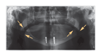
FIGURE 8A. The airway is superimposed as a radiolucent band over the right and left ramus of the mandible (yellow arrows) in this pantomograph.
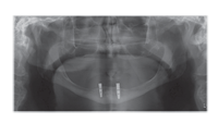
FIGURE 8B. This pantomograph is lightened to show the intact mandible in the area of the superimposed airway.
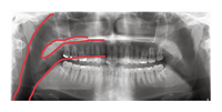
FIGURE 8C. The superimposed airway is visible in this pantomograph.
VERTEBRAL ARTERY
In all panoramic images, clinicians should be aware of the canals of the vertebral artery. They bilaterally and vertically ascend through the transverse foramina of the vertebral bodies before turning to enter the foramen magnum. This artery is a great mimicker of pathology, such as multiple myeloma with its round, well defined, almost punched out appearing radiolucency in the cervical spine, usually seen at the C2 to C3 level (Figure 10).
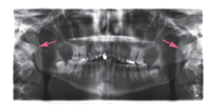
FIGURE 9. Anterior arch of the atlas is superimposed on the ramus and condylar neck, bilaterally.
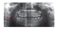
FIGURE 10. The transverse for amen contains the vertebral artery, which is commonly mistaken for pathology.
CONCLUSION
Dental professionals are committed to ensuring the oral health of their patients, which includes taking and examining digital radiographs that may sometimes depict anatomical structures mimicking pathology. Clinicians must remain current on their knowledge of anatomy to ensure correct interpretations of such imaging.
REFERENCES
- White SC, Pharoah MJ. Oral Radiology: Principles and Interpretation. 6th ed. St. Louis: Mosby; 2008.
- Iannucci J, Howerton LJ. Dental Radiography: Principles and Techniques. 4th ed. Philadelphia: Elsevier; 2011.
From Dimensions of Dental Hygiene. February 2014;12(2):34,36–38.
