 DIIGNAT/ISTOCK/GETTY IMAGES PLUS
Avoiding Errors in Digital Radiography
With most dental practices having already made the switch from film to digital, oral health professionals need to consistently evaluate their technique to ensure they are effectively capturing patient images.
Dental radiographs are an integral part of comprehensive patient care. Today, many dental offices are using digital radiography; however, obtaining a diagnostic image with a direct digital sensor can sometimes be more challenging than with film or a phosphor storage plate (PSP). Exposing radiographs on intraoral film—which is pliable and conforms around the tissue—is often more comfortable for the patient and easier for clinicians to use, but it also emits higher doses of radiation than digital imaging. Coupled with the speed and efficiency of digital imaging, it is now the preferred method for dental radiography. This article will review the development and integration of digital technology in addition to errors to avoid in the dental hygienist’s quest to obtain high-quality digital radiographs.
According to the American Dental Association (ADA), approximately 90% of United States dentists use digital intraoral radiography.1 Additionally, dental and dental hygiene schools are integrating digital radiography into their programs in increasing numbers. In my own survey of 13 dental hygiene programs in Ohio, only one still used film radiography in its curriculum. As digital imaging becomes more popular, dental team members need to understand proper exposure techniques and keep up to date on available accessories to ensure patient comfort and compliance.
Charge-Coupled Device
In 1987, a French dentist, Frances Mouyen, developed the first digital radiography system called RadioVisioGraphy (RVG).2 Paul Suni, a Silicon Valley-based engineer, is credited with creating the charge-coupled device (CCD) image sensor technology that enabled the RVG to be incorporated into dentistry. The CCD works by creating an image using pixels.3 After the silicon inside the sensor is exposed to radiation, it converts to an image that is displayed on the computer.4 The CCD, commonly referred to as a solid-state sensor, is a direct digital sensor, and is available in both wired and wireless versions. Both types produce a near instantaneous image. Since its inception in 1987, the CCD has undergone a variety of modifications, making it more comfortable and easier to use, in addition to improving image quality. The complementary metal-oxide-semiconductor is another type of direct digital sensor that uses active pixel technology.2
Phosphor Storage Plate
The PSP was introduced to dentistry in the 1990s. It contains a plastic base composed of europium-activated barium fluorohalide.4 The phosphor layer captures the latent image, which is then scanned to produce an image. The process of exposing and processing a PSP is similar to film, as are the techniques needed and potential errors. Processing issues, however, are nonexistent with the use of digital sensors but error—such as light-related fading, scratches, and fingerprint—can still occur on PSPs.3
Common Errors in Digital Radiography
Images obtained via digital radiography are not always free of technique errors. Digital sensors need to be placed in the oral cavity in a slightly different manner than film, and manipulating around tori or other malformations in the mouth can be a bit more challenging, as sensors are rigid. In general, digital sensors need to be placed more toward the midline.5 Also, a beam alignment device may assist the radiographer in proper placement.
According to the ADA, receptor holders are recommended for all periapical and bitewing exposures.6 These devices reduce the need for retakes by aligning the receptor into a parallel position to the long axis of the tooth. A parallel receptor results in a more diagnostic image because the central beam is perpendicular to the long axis of the tooth, which reduces horizontal and vertical angulation issues.
A parallel receptor position is not always easy to obtain with digital sensors due to the increased thickness of the receptor. The smaller recording dimensions of a digital sensor and a nonparallel position between the tooth and image receptor are the main causes for many digital imaging errors.7 Dental film has a larger recording dimension than a digital sensor, which means that more of the anatomic structures will be recorded. In one study of CCD sensors, the active areas of the CCD ranged from 0.802 mm to 0.940 mm, which is significantly smaller than film, which has an active area of 1.235 mm.2 To accommodate the smaller recording area of digital sensors, the vertical angulation may need adjustment.
One common error when obtaining periapical images using CCD sensors is not recording the apices of the teeth. In a diagnostic periapical image, a quarter of an inch of bone should be visible beneath the apex to allow a complete diagnosis of the periapical region. Likewise, the entire crown of the tooth should also be visible in order to examine for disease. To compensate for the decrease in recording area and reduce the risk of cutting off the apices when using a sensor, the vertical angulation may need to increase slightly, which may result in foreshortening or a steep position indicating device (PID) angulation.7 To increase the vertical angulation, initially line the PID up so it is flush with the ring of the beam alignment device and then move the PID slightly so that it points more toward the crown of the tooth. The receptor may also need to be placed more toward the midline. If a large torus is present, then the receptor can be placed on the opposite side of the torus. The radiographer needs to be careful not to foreshorten the image too much, as this may distort the image.
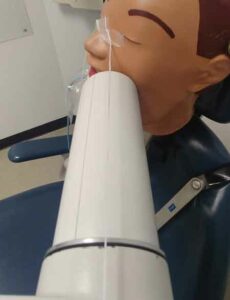
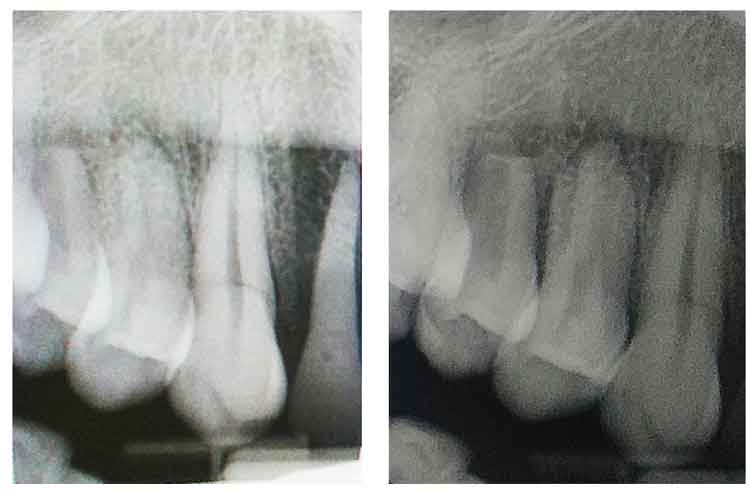
Another common error in both film and sensor image acquisition for periapical and bitewing radiographs is improper horizontal angulation, resulting in overlap of the interproximal contacts. This occurs when the central beam is not perpendicular to the receptor and the area of interest, which is often caused by the receptor not being parallel to the long axis of the tooth. Overlap can also occur when the central beam is not directed through the contact areas. The maxillary canine image is difficult to obtain without causing overlap between the distal contact of the canine and first premolar. This is due to the natural anatomic curvature of the palate, especially when using a rigid digital sensor. One method to decrease the canine/premolar overlap is to place the receptor more posteriorly (Figure 1) and align the PID with the beam alignment device accordingly (Figure 2). Notice in Figure 1 that the image on the right has less overlap between the canine and first premolar but has lost the distal surface of the lateral incisor.
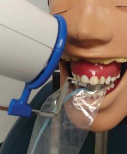
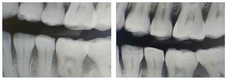
Another error in bitewing exposure is missing the distal of the canine on the premolar image and unequal distribution of maxillary and mandibular teeth. To achieve a diagnostic bitewing image, the radiographer must assure proper receptor position as well as proper horizontal and vertical angulation. Figure 3 demonstrates a good premolar bitewing on the right and an acceptable bitewing on the left. The image on the left was exposed first, then the horizontal angulation of the PID was repositioned to open the contacts more, and the vertical angulation was adjusted slightly to ensure equal distribution of the maxillary and mandibular teeth. This was accomplished using tabs (not beam alignment devices) and aligning the central beam to the space between the nose and the medial or inner canthus of the eye (Figure 4). A similar adjustment occurred with the molar exposure (Figure 5) where the central beam is perpendicular to the outer canthus of the eye. Notice that this dental X-ray training replica has third molars, and this adjustment may not work to open contacts between second and third molars, nor was the intention to capture the distal areas of the third molars. This adjustment can also be accomplished using a beam alignment device.
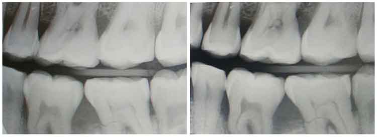
The proper receptor position to capture the distal of the canine on a premolar image with a sensor is to angle the anterior portion of the sensor toward the canine on the opposite side. Again, this is to compensate for the decreased recording area on the receptor. If mandibular tori are present, the receptor should be placed as far away from the tori as possible and can rest on the tongue if needed. Performing little adjustments on sensor imaging techniques can go a long away to increasing the quality of a diagnostic image.
Patient Comfort
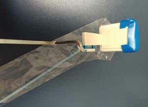
Adjusting the placement of these rigid sensors can make the procedure slightly uncomfortable for the patient. This decrease in comfort may cause the patient to move or remove the sensor before the image is acquired. One study demonstrated that a PSP is more comfortable than a CCD, so placement may need to be adjusted to compensate if using digital sensors.4 One way to make the sensor more comfortable is to use a product to soften the edges. These sticky cushions soften the edges of the sensors, so the rigid edge is not resting directly on bone (Figure 6). These are extremely beneficial in anterior regions.
Another way to increase patient comfort is to use a size 1 receptor for anterior images. There is a 6 mm difference in height and a 0.5 mm difference in length (0.5 mm height and 6 mm length when vertical) compared to the size 2 receptor.7 Using this smaller receptor in the anterior regions may not allow the radiographer to capture all of the necessary structures in three maxillary anterior images so four images are often exposed.
Aside from slight discomfort and minor technique adjustments, the radiation exposure to patients can be up to 90% less when using digital radiography compared to using E speed films so it is worth the time and effort to improve digital radiography technique.
Conclusion
When using sensors in dental and dental hygiene treatment, patients should be educated on the benefits of digital technology compared to film. Increasing patient comfort and modifying imaging techniques to accommodate the digital sensor may increase the quality of periapical and bitewing images and increase patient satisfaction.
References
- ADA News. New ADA standard on digital radiography quality assurance available for download. Available at: click here. Accessed July 10, 2021.
- Jayachandran S. Digital imaging in dentistry: a review. Contemp Clin Dent. 2017;8:193–194.
- Çalışkan A, Sumer AP. Definition, classification, and retrospective analysis of photostimulable phosphor image artefacts and errors in intraoral dental radiography. Dentomaxillofac Radiol. 2017;46:20160188.
- Cederberg MA. Digital imaging sensors in dental radiography. Available at: click here. Accessed July 10, 2021.
- Spiller MS. Essential tips for dental radiographer. Available at: click here. Accessed July 10, 2021.
- American Dental Association. Dental Radiographic Examinations: Recommendations for Patient Selection and Limiting Radiation Exposure. Available at: click here. Accessed July 10, 2021.
- Iannucci JM, Howerton LJ. Dental Radiography: Principals and Techniques. 5th ed. St. Louis: Elsevier/Saunders; 2016:66, 216.
From Dimensions of Dental Hygiene. August 2021;19(8):16-18.

